Tutorial

Embedded Electronics Tutorial Series - Part 2
by p2 | July 3, 2013 | 2 comments
In this tutorial I’ll provide step by step instruction for writing firmware and uploading it to Pinguino. We begin by downloading the Pinguino IDE and finish by writing simple LED blink program for Pinguino PIC18F2550. You may also require installing Pinguino Drivers before proceeding further, please see this post for installing pinguino drivers: Tutorial - Installing Pinguino Drivers On Windows 7
This tutorial assumes you are on windows based operating system and are using your own pinguino setup with pinguino bootloader v4+ or using prebuilt pinguino board like this. For downloading Pinguino IDE please see the following link: https://code.google.com/p/pinguino32/downloads/list
Pinguino IDE is written in python and it uses SDCC or Small Device C Compiler for compiling and generating Hex files. As of writing this tutorial X.4 is the latest IDE, once you have downloaded it then unzip it and click on “pinguino.exe†to launch the IDE.
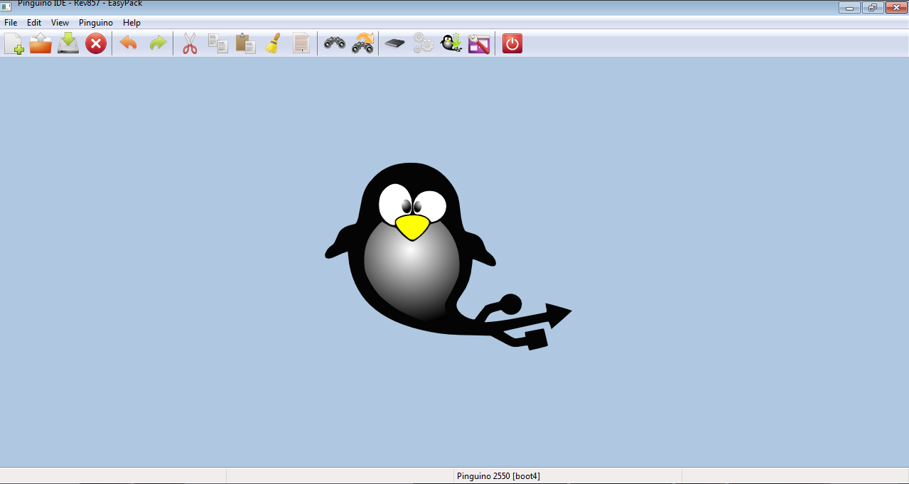
We are now ready to write our first firmware. From the top menu click on File > New, this will open a new editor window, now copy/paste the following code into the editor:
#define USERLED 12
void setup() {
pinMode(USERLED, OUTPUT); // initialize the digital pin USERLED as an output.
}
void loop() {
digitalWrite(USERLED, HIGH);
delay(50); // wait for 50ms
digitalWrite(USERLED, LOW);
delay(50); // wait for 50ms
}
And from top menu select Pinguino > Compile to compile this code. Once compilation is complete you can see in the log window in the footer of IDE that if code is compiled successfully or if there is some error in code. This process will generate a HEX file which is required by the microcontroller.
Now connect your Pinguino with the USB cable and from top
menu select Pinguino > Upload, this will upload the firmware on the
microcontroller and you could see the LED blinking. If you are using your own setup then you need to connect LED on pin number 12,i.e. positive pin, anode of led on pin 12 and other led pin to ground through resistor. Incase if uploading fails
then check if you have selected the correct board, to do this click on Pinguino
> Selector Board and click on the following radio buttons:
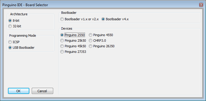
- In the Architecture group select 8-bit
- In Programming Mode group select USB Bootloader
- In Bootloader group select v4.x
- In Devices group select Pinguino 2550
The above code is self-explanatory, but you need to understand that every input/output pin of microcontroller can be set either as input pin or as an output pin. If you set any pin as output pin then it can supply 5v on that pin and if you set any pin as input it can sink some current supplied on that pin. On pic microcontroller both output and input pins current is limited by an internal resistor.
In the above code, pinMode() defined in the setup function sets the pic microcontroller pins to input or output. Since we want to supply some power to the LED to make it glow we make the LED pin as output. The loop function runs continuously executing whatever in defined inside it, if it reaches end then it goes back to the beginning of loop function and start executing the code. The digitalWrite() when set high provide 5v to the led pin and when set low connects led pin to ground. Delay() simply waits for the number of milliseconds provided as the parameter. If you change delay(50) to delay(500) you can see LED glow every 1 second.
The setup function runs only once and the loop function runs repeatedly, therefore we have used setup function to initialize our setting of input and output pins and we have defined actual task in the loop function so that it gets executed repeatedly. There is also one more function the interrupt() function which runs whenever an exception occurs externally or internally, but we will learn more about interrupts in some other tutorial so that by that time you get acquainted with basics of pinguino.
For this tutorial we will end it here, but in the next tutorial we will learn about breadboard and build breadboard power supply to use pinguino without USB power and interface pinguino to other external components.
Hello I’ve got a question. What is the different between bootloader V.4.9 (your boostloader) and the V.4.8 from pinguino website?
its the same, v4.9 is also released by pinguino team, it have some bug fixed.