Tutorial

Embedded Electronics Tutorial Series - Part 3 -Solderless Breadboard
by p2 | August 1, 2013 | Post your comment.
Every electronic project idea starts with a solderless breadboard therefore I am writing this tutorial to explain how to use it. Solderless breadboard are great for quick assembling and connecting all the components together for your project. As the name infers you do not need to solder any component therefore you can create temporary circuits that can be changed as required.
Let me provide you an example, look at the second figure below. You can see the black lines, two horizontal and many of them vertical, the vertical lines or columns (A1, B1, C1, D1, E1) are internally connected. Similarly the two horizontal black solid lines labeled X and Y is also internally short or joined for all the holes that are on it.
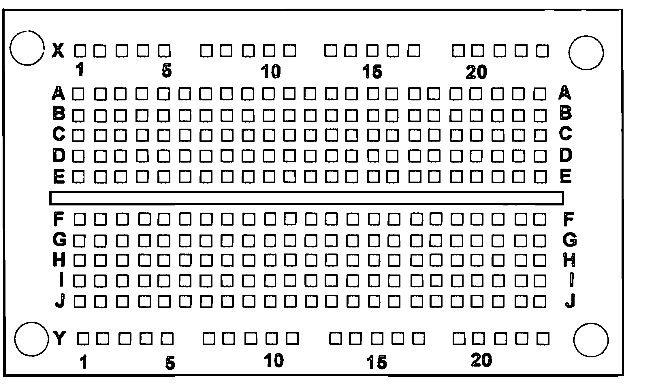
In each hole a wire or a pin of gauge #22-#30 can be inserted. These holes are called tie points and are aligned into 2.54mm grid, the standard DIP package pins uses this grid, so you can use any components, like IC, led, resistors, diodes, capacitors, transistors and DIP packages. Since breadboard provides internally connected paths therefore we can connect different semiconductor components in parallel or serial.
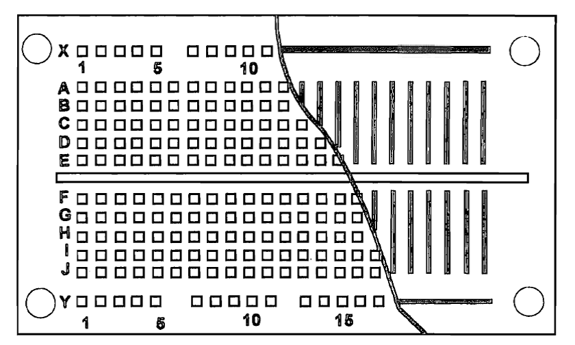
Internal structure of bread board, you can see the vertical lines, columns are internally shorted and the two horizontal line, two rows are internally short.
To build any circuit on breadboard just place the component on the tie points as per your schematic and push it so that part pins goes inside the tie points. Since internal connection is limited to a particular column or row so to connect different components or columns to each other you can use wires. When inserting any component on breadboard keep in mind that component pins should be aligned row wise before you insert it, for example if I want to connect a three pin device then I’ll align device as the first pin should go into A1 second in A2 and third in A3.
As I have mentioned in the previous tutorial let’s build a simple 5v power supply on breadboard for powering our circuits. To make the power supply we will need these components:
A 5v Regulator IC, LM7805 (http://anceop.com/?action=page¶m=viewProduct&id=99757)
A breadboard (http://anceop.com/?action=page¶m=viewProduct&id=41427)
100uF, 10uF and 100nF capacitor
A LED
A 1k Resistor
And some wires
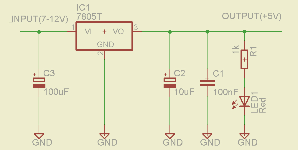
But before we built the above schematic on breadboard let me first explain the use of each and every component in schematic. If you know about voltage regulators, capacitors and resistors you can skip the following text since I have explained basics of these here. In this circuit we have used six components, 3 capacitors, 1 resistor, 1 led, 1 voltage regulator and some wire. Among the six the main component is the 5v voltage regulator, LM7805, in the schematic part labeled with IC1 is our 5v regulator IC. Its function is to step down higher voltage (up to 30volts) to 5volts and provide maximum current up to1 ampere. To make it work input voltage should always be greater than 5volts. Therefore with this circuit we can use 7v to 24v battery or dc wall adapters to get 5v for our need. We are specifically building 5v supply because almost all the microcontrollers, sensors and electronic circuits work on either 5v or 3.3v, since we will get 5v from this circuit we can again use a 3.3v regulator to get 3.3v out of the same circuit. Below is the connection diagram of LM7805, as you can see it is a three pin device with a common ground. That means our –ve input supply will be common with our –ve output supply.
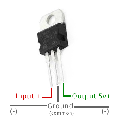
Connection diagram of 5v Regulator IC
The next component we are using is capacitor, it is not a vital component for our circuit but to improve output we are using it. Its function is simple, to store charge. As battery store charge similarly capacitor also store charge but its capacity is very very little as compared to battery. Flowing of charge is responsible for current and voltage generation. To understand capacitor consider two water pipes connected to a tank as shown in below figure, water flows into tank from one pipe and leaves the tank from another pipe. Capacitor can be considered as a water tank and water itself as charge, so capacitor basically accumulates charge and releases it.
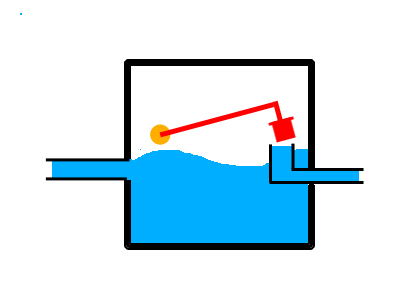
Valve Opened for AC
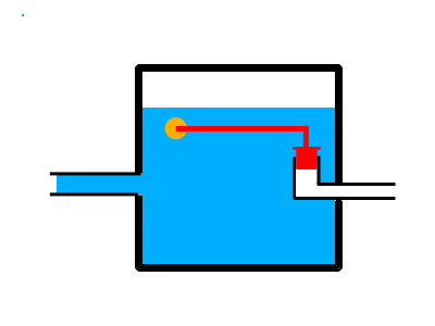
Valve closed for DC
One of the properties of capacitors is that it allows AC (alternating current) to pass through and blocks DC (direct current) this makes capacitors to be used as filter, in our power supply circuit we have used this property only. The three capacitors labeled C1, C2 and C3 will filter ripple (AC) or current pulses, and pass them to ground so that we get as much as possible pure DC supply.
Capacitance is measured in Farad. Capacitors come in varieties of size, shape and material but they can be classified in two ways polar and non-polar. Polar capacitors are those which can be connected in only one way, according to their polarity, positive pin (anode) with positive supply and negative pin (cathode) with ground. Non-polar capacitors or bipolar capacitors can be connected in either way, they are not polarity specific. In our power supply schematic above, the 10uF (labeled C2) and 100uF (labeled C3) capacitors are polar and the 100nF (labeled C1) capacitor is non-polar. In a polar capacitor anode and cathode are printed on it, anode is indicated by + sign and cathode with a – sign, alternatively the anode pin is longer than the cathode pin. And in a bipolar capacitor both the pins are equal.
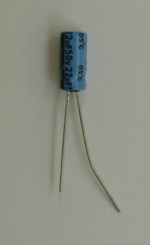
Polar capacitor, 22uF 50V. You can see right side pin is a little bigger than the left one also on the shorter pin side there is a black marking indicating cathod or ground pin. Sometimes instead of denoting capacitor value in uF (micro farad) you may find capacitor value as MFD, which is same as micro farad.
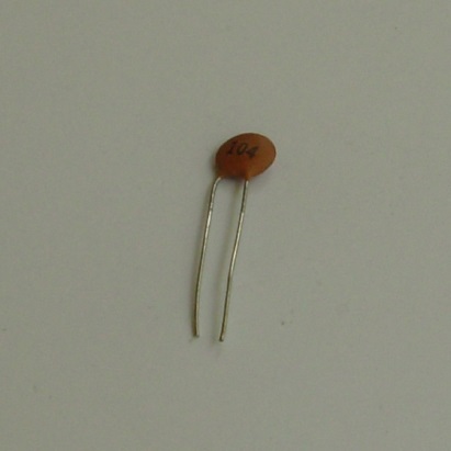
Non-Polar capacitor 100nF 50v both the pins are of equal length.
In our 5v power supply circuit we have also used LED, light emitting diode to provide a visual indication that our circuit is switched on and working, in the schematic LED is connected at the output and is labeled LED1. LED requires a minimum voltage of 2volts and about 5mili ampere current to glow and it is a polarity specific device i.e. its anode (longer pin) is connected to positive supply and cathode (shorter pin) is connected to negative supply or ground. At output we will be getting about 5v and 1ampere, since LED requires much lesser current then that so we need to limit the amount of current passing through LED, this is done by a resistor. If we do not limit the amount of current it may burn the LED.
Next component is resistor its function is to limit the amount of current. In the above water tank example imagine if we squeeze the pipe limiting the amount of water flow at the end of the pipe, similarly resistance limits the amount of current and hence dropping voltage. We are using resistance in series with LED in order to limit the current supplied to LED. In our power supply schematic the component labeled R1 is symbol of resistor. Resistor is a two pin non-polar component and can be connected irrespective of its polarity. Resistance is measured in ohms.
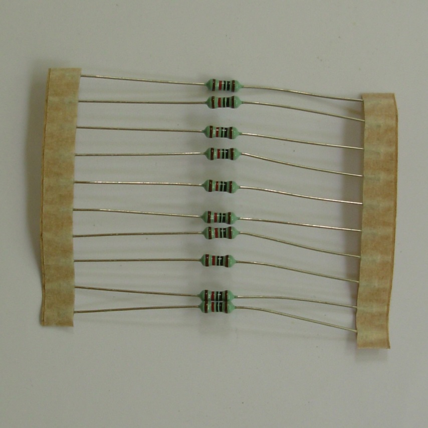
10 resistors of 10 Kilo ohm each
Resistors have different color bands on it to indicate its value, each band can be a digit band, a multiplier band or a tolerance band. The last band is always a tolerance band, the second last band is always a multiplier band and all the other bands are digit bands. Let’s calculate the value of resistance in picture, to get the digit band value we can use the below table:
Black = 0
Brown = 1
Red = 2
Orange = 3
Yellow = 4
Green = 5
Blue = 6
Violet = 7
Grey = 8
White = 9
Resistor has the following band and from the above table we can get values of each band:
Brown = 1
Black = 0
Black = 0
Red = 2
Brown = 1
To get the final value of resistor we first write values of the digit bands followed by one another, this will form a two or three digit number and then multiplying this number with the multiplier band.
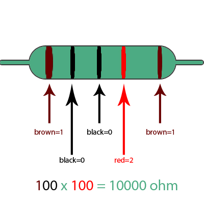
From the first three digit bands we get 100
Next we multiply the multiplier band to this number, here we have second last band to be red which is equal to 2, but we do not multiply it directly rather we pad number of zeros to1, so red band becomes 100 and then multiply it.
100 for Brown Black Black
100 for red (2->100)
100X100 = 10,000 = 10k Ohm
And the last Brown band indicates tolerance of 1% of the total value. Most of the time you may find tolerance band to be either gold or silver, gold means 5% and silver means 10% tolerance. One thing to note here is that first band is always the band which is slightly broader then the rest of the bands and last band is always the tolerance band, to calculate resistance value first look for the slightly wider band on resistor and start from that band only. You can also note from the above resistance picture that the tolerance band is slightly away from the group of bands.
If you find it hard to remember color band table then you can use the following to remember it, this was told to me when I was in school by one of the physics teachers: B B ROY of Great Britain has a Very Good Wife.
If you do not want to remember resistor color codes you can use online web application like this to calculate resistance value: http://www.dannyg.com/examples/res2/resistor.htm. Other than this you can always use multimeter set in resistance measurement mode to measure resistance.
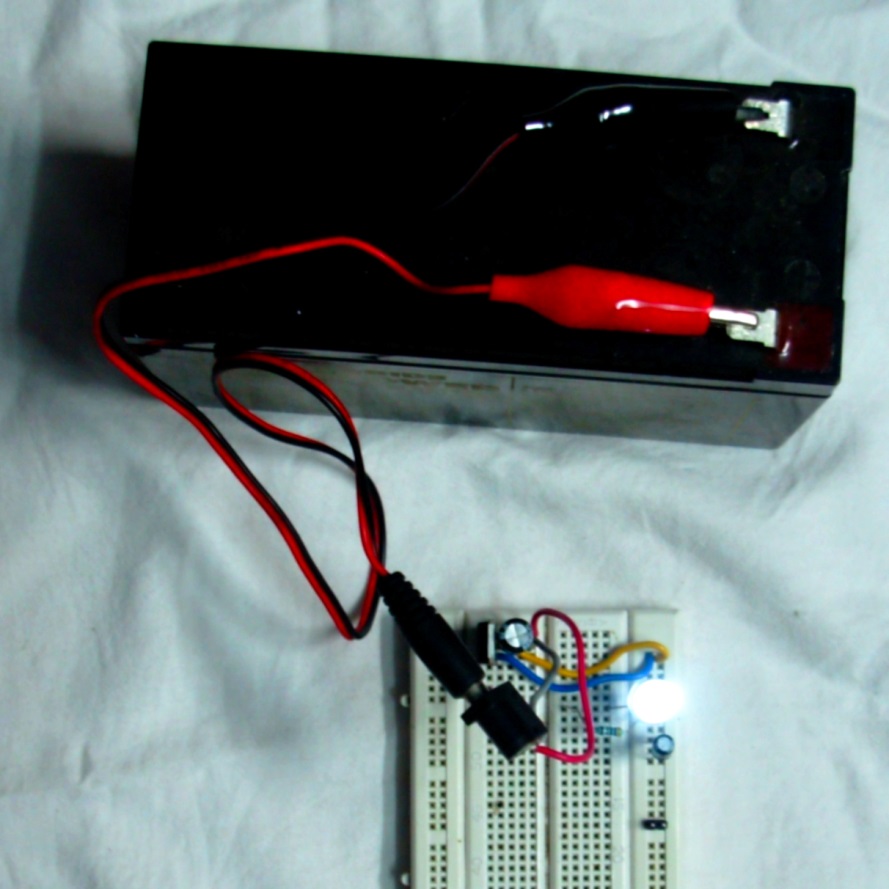
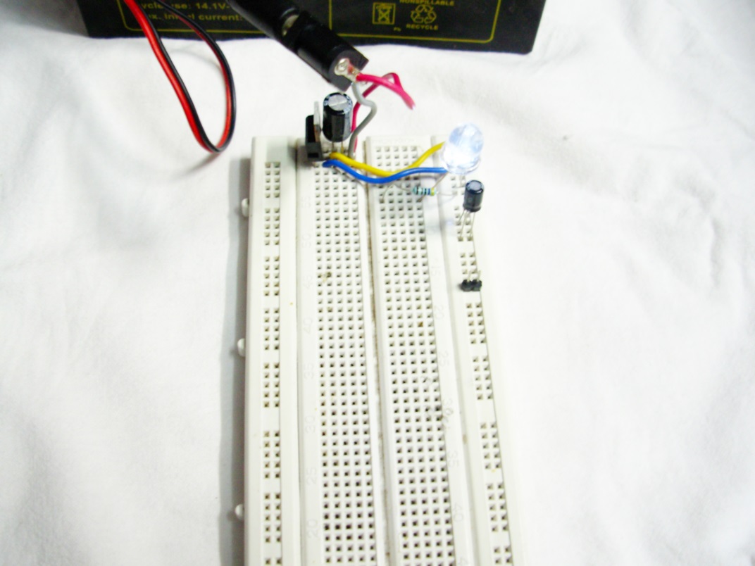
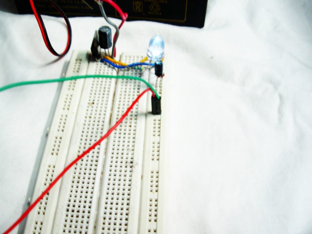
Now we are aware of the purpose of each component used in this circuit, let us connect all the components on breadboard as per the above schematic. For the input power supply connection I have used female DC barrel jack, I have soldered two wires one on the anode pin and other on the cathode pin and connected the other side of the wires to the input of 5v supply.
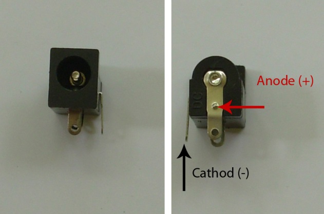
The only advantage of using barrel jack here is that if you have a battery then you can the circuit with alligator cable as I have connected in the below picture and if you need to power through wall AC-DC adapter then you can use that also.

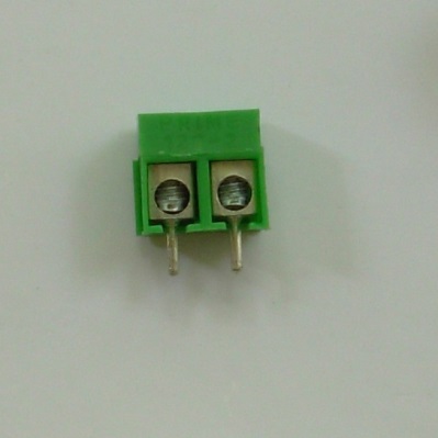
If you have wires coming out of the battery then you can use these screw terminals, they have a slightly bigger diameter pins so you have to push a little hard to get them into breadboard.

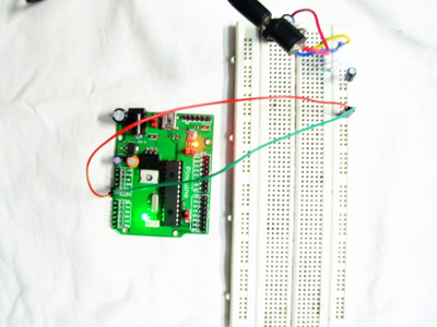
Since I want to power my pinguino board so I have added break away header pins and connected female jumper wire to them so that I can easily connect it to pinguino.

Picture of my setup
That’s all for this tutorial I hope this tutorial helped you. In the next tutorial we will extend this power supply to use transformer and convert ac voltage to dc voltage using diode rectifier circuit and transformer. We will also learn to use adjustable regulators. Please feel free to post your comment and feedback below.
Thank you
If you have wires coming out of the battery then you can use these screw terminals, they have a slightly bigger diameter pins so you have to push a little hard to get them into breadboard.

Since I want to power my pinguino board so I have added break away header pins and connected female jumper wire to them so that I can easily connect it to pinguino.
Picture of my setup

Thank you